From TrueNAS CORE to TrueNAS SCALE

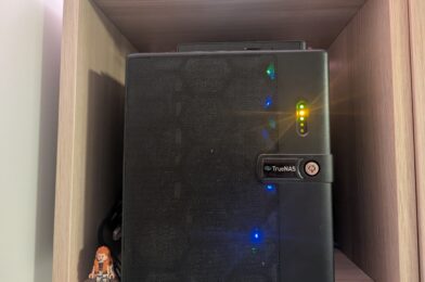
I finally bit the bullet. After years of running my trusty TrueNAS CORE server, I decided it was time to make the jump to TrueNAS SCALE — the newer, Linux-based version that’s now iXsystems’ main focus.

When CORE officially moved into “sustaining engineering” in early 2024 — meaning no more new features, just maintenance and security updates — I knew I had to migrate sooner rather than later. By April 2025, with the release of SCALE 25.04 and the final CORE update (13.3-U1.2), the priority of this task became even greater. However, I knew upgrading would take me quite some effort, so I kept postponing it. Until last week, when the wife was out of town and I could work undisturbed deep into the night for a couple of days while the kids were in bed.

TrueNAS? Core? Scale?

Hold on, not so fast I hear you think. What even are these programs I’m talking about, and why are they relevant?

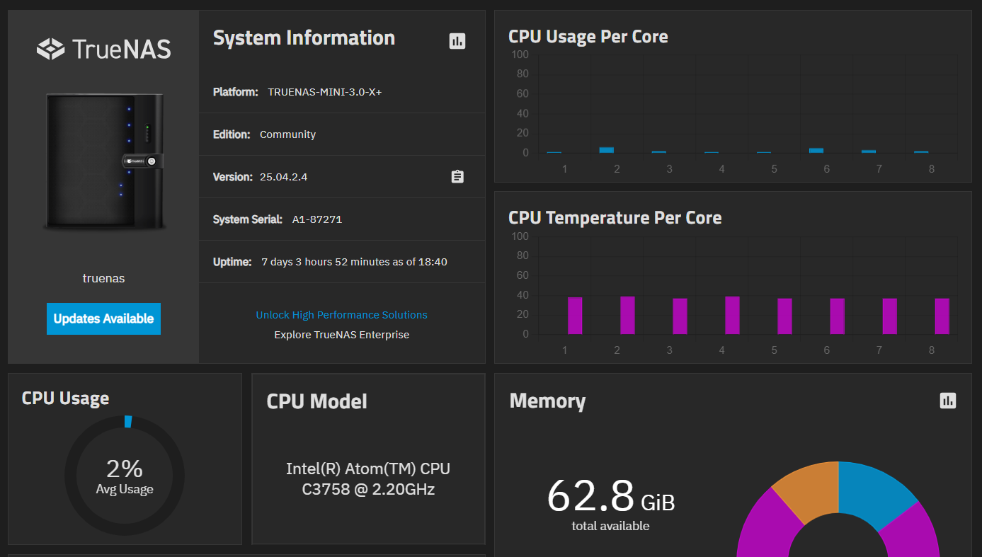
All right, in September 2021 I bought myself a TrueNAS Mini X+ as my new private NAS server. After previously running my website on an Intel NUC, I quietly upgraded to a proper NAS. I kept the NUC solely for Home Assistant, and moved the rest of my smart home stack to the new Mini X+. TrueNAS CORE was the Operating System (OS) I used for my NUC as a home server, so it made sense to continue using it on my new hardware.

TrueNAS CORE is an open-source OS specifically designed for servers and network-attached storage (NAS). It’s built upon FreeBSD and is widely praised for its rock-solid stability.

PXL_20251027_203454912

TrueNAS Mini X+

Also around this time, iXsystems — the company behind TrueNAS — released the first public beta of TrueNAS SCALE, a new OS built upon Linux. In their early announcements, they explicitly wrote: “Production users with standard NAS (NFS, SMB, iSCSI, S3) requirements are still advised to use TrueNAS CORE … SCALE has inherited some of that maturity … but has not completed its software quality lifecycle.”

That was fine by me. I already knew my way around CORE and had a good, stable NAS system running, which I simply migrated to my new hardware.
FreeBSD offers a way to run isolated extra applications through a feature called jails. Programs in jails operate independently from the host system — like mini-sandboxes – but share the same kernel as the host system making them far more efficient than full virtual machines.

Over the last four years, I’d built up a stack of nine jails hosting a total of fourteen different programs:

  • Adguard – blocking ads on my home network.
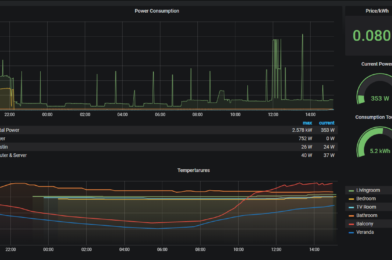
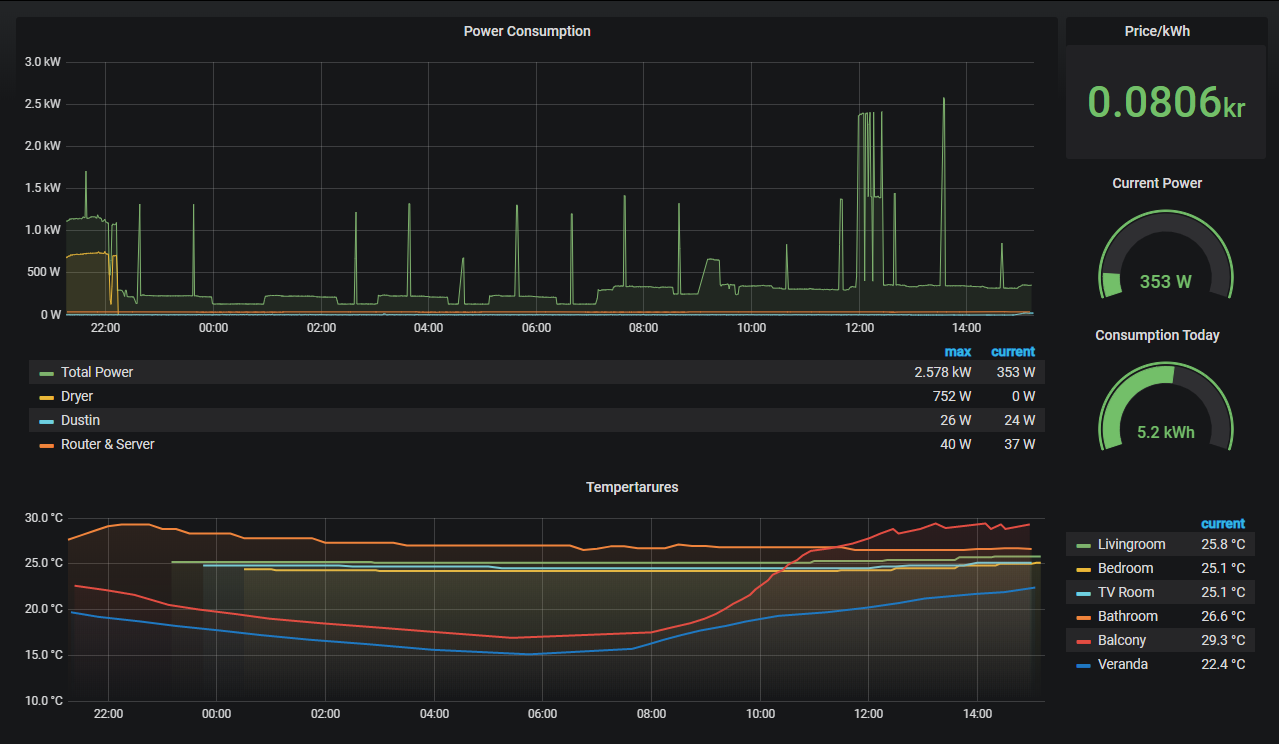
  • Grafana – fancy graphs for showing smart-home data.
  • WordPress – this website.
  • Mosquitto – MQTT server for collecting smart-home data.
  • Nextcloud – a private alternative to Dropbox or Google Drive.
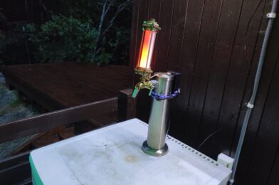
  • Plex – a private alternative to Netflix.
  • Handbrake – ripping DVD’s for my Plex library
  • Radarr/Servar/Readarr/Prowlarr/Transmission – automated torrent indexing and downloading.
  • Nginx Reverse Proxy – allowing access from the internet to my internal programs.

However, as time went on, TrueNAS SCALE matured and began to outpace CORE in terms of features, app support, and active development. By early 2024, iXsystems had officially confirmed that CORE would only receive critical fixes going forward, while SCALE would be the focus for all new functionality. Then, in April 2025, they released SCALE 25.04 alongside what was announced as the final CORE 13.3 update — version 13.3-U1.2 — effectively marking the end of the CORE development line.

And that gave me a bit of a problem.

See, migrating from CORE to SCALE is usually pretty painless — the official tools can migrate nearly all system settings and file shares automatically. However, one of the major exceptions is jails (the other being virtual machines, which I didn’t use). Since SCALE is built on Linux, it relies on Docker containers to run extra applications. Docker containers are inherently different from FreeBSD jails, so they can’t be transferred automatically. That meant I had to rebuild all fourteen of my programs manually, which I expected would be… well, a bit of a pain and pretty time consuming.

I’d actually been keeping an eye on SCALE for quite a while and had considered migrating since version 24.10 (released in October 2024). After a year of postponing — and finally having a few quiet days at home in October 2025 — I decided to go for it: time to future-proof my NAS and take advantage of the new features that SCALE offers.

TrueNAS SCALE 24.10 artwork

Migrating to SCALE

The entire migration process ended up taking a week. As in, I started on a Friday… and wasn’t done until the Thursday after.

Friday evening – Backup & migration

I started by taking backups of all my programs. The migration from CORE to SCALE is a one-way process, so I wanted to be absolutely sure nothing important got lost. Luckily, most backups were straightforward.

WordPress? Used a plugin.
Reverse proxy? Just copied the proxy.conf file.
Radarr and Sonarr? Clicked the handy “Backup” button.
Nextcloud was the only one that needed a bit of command-line work to dump the MySQL database.

All in all, after about two hours, everything important was backed up. Since my files would still be accessible after the migration — and I also have an off-site backup — I didn’t bother backing up large media files like my Nextcloud data or Plex library. I just focused on configuration, databases, and anything I couldn’t easily recreate.

For completeness, I also backed up all my NAS settings, certificates, and took screenshots of important automation schedules. That turned out to be unnecessary, because the OS migration itself was incredibly smooth. In CORE, go to Settings -> Update, choose SCALE 24.04 and press Download & Apply. One coffee later, my Mini X+ rebooted and greeted me with the shiny new SCALE login screen.

To my surprise, all my system settings — users, permissions, certificates, shares — had migrated perfectly. By that time it was getting late, so I decided to quit on a high note and leave the app setup for the next day.

My new TrueNAS SCALE dashboard.

Saturday evening – Reverse proxy & Docker containers

After some initial poking around (okay, I admit it — I tried to install all my apps simultaneously because I’m impatient, which naturally failed spectacularly with a flood of error messages I didn’t understand), I figured it was best to start by getting the reverse proxy back up and running. After all, most of my other apps rely on it, and it didn’t seem like the most complicated one to start with.

The thing with Docker containers is that their filesystem is normally hidden from the user. Depending on the app, SCALE allows you to mount certain directories as easily accessible folders on the host system. This was new to me, and it forced me to think about a good way to organize everything. It also took me a while to realize that, for this to work, both the folder and all parent folders you’re mounting into need the correct permissions — otherwise the mount fails and the app won’t start.

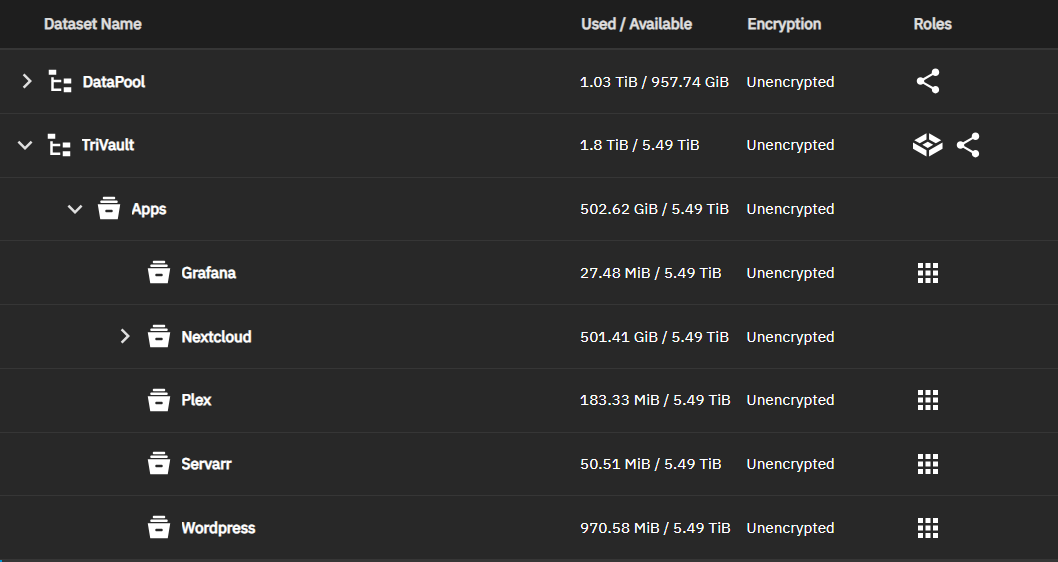
To keep things simple, I ended up creating a new dataset in the root of my filesystem called Apps. Inside that dataset, I created a child dataset for each app I wanted to mount. The main Apps dataset has broad access permissions, while each app dataset is tailored to its specific needs. I figured that should be secure enough for my setup.

My dataset structure after the migration.

That evening, I managed to get the reverse proxy up and running. As a bonus, I now had a fancy web interface to configure it – something I didn’t have before. I also got AdGuard up and running. While researching how to set up the reverse proxy, I stumbled across something called Cloudflare Tunnel, which might allow me to get rid of the reverse proxy. Hmm… well not now – let’s try and reach parity with the old system first.

Sunday evening – Formula 1

Sunday was race day, so priorities were clear.

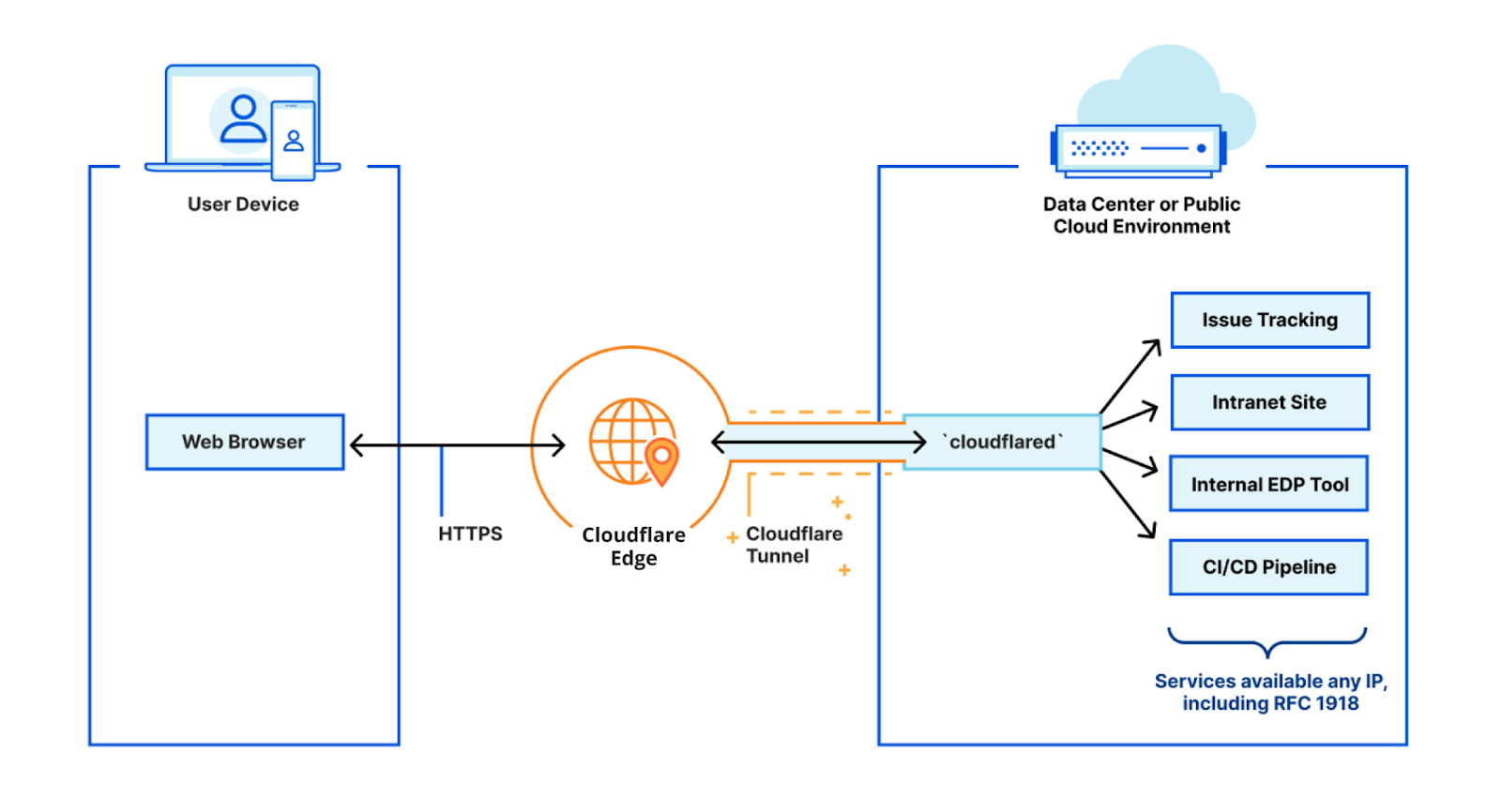
Though before the race I looked some more at Cloudflared (Cloudflare’s tunnel client). It’s a small program that creates a secure, outbound tunnel between my home server and Cloudflare’s network. This lets you access services like Nextcloud or WordPress remotely — no open ports, no self-signed certificates, no dynamic DNS updates. Everything runs “securely” through the tunnel. I say “securely”, because the downside is that Cloudflare is in charge of security, and because of that in theory can see all my network traffic.

Monday – Nextcloud

Monday was dedicated entirely to Nextcloud.

The official Nextcloud app in Truenas SCALE uses a PostgreSQL database, opposed to the MySQL database I was using previously – and had a backup for. My inexperience using docker, lack of a computer running Linux and general inexperience with databases meant that it took me a good part of the day to figure out how to convert my MySQL database into a PostgreSQL database. For those interested, what worked in the end for me was to:

  1. Set up 4 docker containers:
    – Nextcloud – This is where we eventually want the database to go.
    Pgloader – A tool to convert between MySQL and PostgreSQL.
    MySQL:8.0 – Important this is version 8.0 or lower, otherwise PgLoader doesn’t work.
    PostgreSQL – a separate container to load the database into.
  2. Load the MySQL backup into the MySQL container.
  3. Use PgLoader to migrate the database from MySQL to PostgreSQL.
  4. Dump the PostgreSQL database and restore it into the Nextcloud container.

Apart from the database, I also had troubles mounting my files correctly to the docker container, and getting the permissions of the datasets to match. So in addition I used a lot of time making sure Nextcloud could actually find my files. I left out a lot of troubleshooting here, the entire process took me almost 14 hours to get right.

Nextcloud Loginpage

My Nextcloud login page. I was very happy when I saw this again.

Tuesday – Cloudflared, Radarr/Sonarr, Plex

On Tuesday, I gave Cloudflare Tunnel a proper test. I disabled my reverse proxy, set up Cloudflared, and configured it to expose my Nextcloud instance to the internet. So far, performance looks great — and it’s far easier to maintain than my previous Nginx setup. I’ll be testing this out to make sure it performs well in the upcoming weeks/months, but it is looking promising and an easier to use alternative than my reverse proxy setup. And I trust that one of the largest online security providers in the world is able to handle my data securely and discretely – their entire business model is based around that.

On Tuesday I also re-installed my Radarr/Servarr and Transmission setup. Radarr (for finding movies) and Servarr (for finding series) luckily had easy to use restore functions, so setting them up was very easy, especially after all my troubles from the day before. Transmission is just a downloading tool, so no need to do any restoring there.

I also re-installed Plex. The Plex backup itself worked flawlessly, so all my settings were still there. It however turned out that I had messed up the access permissions to my movie files – I suspect it was an issue with the dataset they were in – but instead of trying to find out how to fix it I decided to start from scratch, delete everything and re-download/re-rip movies when I see the need for them. No big deal, after my wins with the other apps (getting Nextcloud back was much more critical) I was comfortable taking this loss. And it freed up a good chunk of hard disk space.

Plex

Plex (my personal Netflix) back up and running.

Wednesday evening – Grafana & InfluxDB

Wednesday was for the smart-home dashboard Grafana (and InfluxDB).

On CORE, I had used the official Grafana plugin, which came bundled with InfluxDB v1. On SCALE, the Grafana app no longer includes InfluxDB, so I had to install both separately.

The difficulty here was the age of my influxDB database. When I set up the original Grafana plugin in 2020 InfluxDB v2 had just come out, but ‘everything’ still ran on the older v1, including the plugin. This had never been updated, so getting up to speed on the ‘new’ v2 nomenclature and updating Home Assistant – which pushes data to the database – to use the new api took a bit of research. But after an hour or 2 I also had this up and running again.

Grafana dashboard.

Thursday evening – WordPress

Lastly, I turned my attention to WordPress and getting the website you’re looking at now back online. I’d actually tried to get a WordPress app running earlier in the week, but for some reason it kept failing on me. In the end, I discovered that one of the storage mounts in the app settings was causing the issue — specifically the WordPress MariaDB Data Storage. Since I didn’t need external access to that anyway, I left it internal to the Docker container. With a fresh WordPress site I used a migration tool to restore my website and all its settings.

That was the last piece of the puzzle. For those paying attention I did not migrate the Mosquitto app, as that had actually become obsolete a few months earlier due to changes in my smart home setup. After a week of work I had successfully migrated from CORE to SCALE.

So what now?

SCALE makes it easy to pass through a GPU to your apps. My Plex setup will benefit a lot from that — it enables GPU Transcoding, which should let it stream high-definition video across the network more smoothly and (hopefully) get rid of the occasional stuttering we’ve been seeing. I have already ordered a new GPU for exactly this purpose.

On top of that, the app library in SCALE is much larger than the old plugin library in CORE, so I’ll have plenty more apps to experiment with in the future. And since everything runs as Docker containers, I can even spin up my own if something isn’t available as a pre-built app.

I do enjoy tinkering with new tools and software, so I’m sure it won’t take long before I find some new, creative ways to expand what my NAS can do.

Custom light posts for the cabin

Sometimes when I’m browsing the web I get inspired by whatever it is I’m looking at. That so happened when I stumbled upon the following picture:

concrete-lamp

A small light post made out of concrete which houses a single spotlight that shines downward and scatters the light down on the ground. The description said it was easy to make a mold out of wood, and pour concrete in it. I think it would be great to have some small light posts at our cabin to light up the path from the parking area to the cabin. I imagined these kind of lights to fit really well in the area since they do not take up too much space, give a nice indirect glow of light low at the ground. I figured if I make them myself they hopefully would not get too expensive either.

Materials

Obviously, to make the mold I’d need some wood. I settled on cheap spruce wood for the vertical parts and some oak wood for the base purely because I had a piece laying around and it seemed a bit stronger. Additionally I bought:

  • B30 concrete.
  • Electrical tube.
  • Electrical boxes.
  • Brown & blue electrical wire.
  • GU10 light holders.
  • Fishing wire.
  • 200mm bolts.
  • Screw rods.

I learned that concrete is not to be confused with cement. Cement is an ingredient of concrete, which I found out whilst shopping for this project. I also learned that there are different types of concrete, indicated by the B-number. B30 is appropriate for outdoor use, hence why I went for this.

The 200mm bolts stick out of the bottom of each light and will act as an anker once I mount the lights at the cabin. The screw rods I figured would act as some cheap form of reinforcement. The fishing wire is to keep the electric tube and screw rods in place while pouring the concrete.

Since I’d be making a reusable mold I’d decided to try and make 6 light posts. Why 6? I don’t know, it just felt right.

The build process

The building process of the mold was fairly straight forward. I’d labelled all the sides (A, B, C & D) and made sure to use 3 screws between all sides to firmly hold them together in a square. Side A would hold the diagonal piece and cut-out for the lightbulb, whilst side C would hold the electrical box.

IMG-20230530-WA0000
IMG-20230530-WA0002

The sides mount on top of a base plate using a total of 8 screws. I also used some foam in between the base plate and the sides to try and make them watertight and thus prevent concrete from leaking out while it was drying.

PXL_20230604_145020158

Cross section of mold before pouring the concrete

The screw rods are hanging in the mold with the use of fishing wire, and run most of the length from top to bottom. The electrical box and tube are held in place using hot glue. After everything was screwed and glued together I mixed the concrete in small batches (~2kg per batch) and slowly filled the mold with concrete. Then I’d have to wait at least a day for the concrete to dry.

The first build

The first light post came out decent, but had some flaws.
Firstly, in this first build I’d opted to mount the GU10 holder before pouring concrete instead of leaving a cut-out. This resulted in the holder filling up with concrete and the concrete becoming slightly electrified when 230V is applied, which makes your fingers tingle when you touch it.
Secondly, I found that it was hard to remove the cut-out for the lightbulb without damaging the concrete. I figured this was due to three reasons; firstly I’d been impatient and removed the light post from the mold after 1 day. Concrete officially takes 28 days to fully dry out, and removing it after 1 day meant the concrete was still quite brittle. Secondly since I did not use any lubricant on the wood it got stuck to the concrete. Thirdly the concrete’s thickness between the cutout and the side of the light post was relatively thin, so a small amount of force would cause this part to break.

IMG-20230602-WA0000
IMG-20230602-WA0003
PXL_20230602_150805912

Left picture: the light post after it came out of the mold. Top right picture: the cut-out. Bottom right picture: the first test. Note here that the concrete has broken off in front of the lightbulb due to removing the cut-out.

The other light posts

Having learned from the first light post I’d now made the following improvements:

  • Add a cut-out for the GU10 holder instead of pouring it directly in the concrete.
  • Wait at least 2 days before taking the light post out of the mold after pouring.
  • Pretreat the cut out parts with oil, so that they stick less to the concrete and are easier to remove.
PXL_20230602_202802128

The second light post, tested in twilight.

The second light post I poured came out better, however it was still difficult to keep the concrete between the cut-out and the side intact as it was just so thin. This is a problem that all subsequent light posts also had, and my solution was to try and glue together the bits that fell off as best as I could and treat the lights after they’d been installed with a concrete-repair solution – in other words a problem for future me.

When I knew this method worked well enough, I sat down and made all the parts for the other 4 lights I wanted to make.

Snapchat-1607147421

Mass producing the parts for the other 4 lights.

Pouring all 6 lights took me around 3 months. Before shipping them off to the cabin I tested them all and made sure to cap off the electrical box so that no water/animals would crawl into them while they were being mounted at the cabin.

PXL_20230828_132329901

The final 2 light posts, standing upside down and ready for transport.

Mounting at the cabin

My hope was that I could simply place the light posts at the cabin in the ground and that the bolt on the bottom of each light post would keep them in place. However when testing this it became apparent that this just would not work, and that they would fall over very easily. So I reverted to more concrete pouring. For this I dug out a hole until I hit the rock bottom. Then I placed large cardboard tubes in the hole, which I filled up with concrete. I also pushed some 20cm long PVC pipe (sealed on each end) in the middle of the drying concrete and held that in place with a brick.

PXL_20230908_142415694
PXL_20230908_142407053

What is the purpose of the PVC pipe you might ask? Well, after a day of drying I would remove the PVC pipe, fill up the hole with fresh concrete and place the light post with its pin inside this fresh concrete, whilst the weight of the light post would be supported by the concrete poured the day before. This allowed me to place the light posts flush with the concrete, and allowed for some adjustment to make them stand exactly straight before the concrete would dry. Genius, right? 

PXL_20230909_090741340

This picture shows 4 lights. Can you find them all?

I ended up placing 5 lights. 2 next to the parking space and 3 next to the path. The sixth light has as mentioned some electrical issues, but we might be able to place it elsewhere and powering it using 12VDC.

After putting them up (& waiting 5 months for the winter to pass) I swapped the backplate for a waterproof junction box, and wired them all up using outdoor-rated cabling.

PXL_20240413_101314738

The junction box. Here shown during installation.

I also installed a 16A Zigbee Mini Smart Switch to control the lights through Home Assistant. This particular version also has the option to add a manual switch, which we might add in the future. Lastly I buried the cable connecting the light posts to a depth of 1-10cm, and after that it was time to wait for twilight and enjoy a job well done.

End result

PXL_20240413_175749770

The first test. They all light up!


PXL_20240413_183049402.MP

In the dark. This is when they look their best.

I really enjoyed this project, even though it took me almost a year to finish it. Not only did I learn a thing or two about concrete, but we now also have some beautiful lights at our cabin, which’ll hopefully stand there for many many years.

Custom Smart Thermostat

Last year I programmed my own custom smart thermostat using Home Assistant and a couple of WiFi enabled heaters. I’m writing this article mostly to document the process of how I control my heaters in the living room and to hopefully inspire others to implement their own solution. I will also try to update the numbers in this blogpost as I make changes to it in the future.

It was important for me that this system would work the entire year round and always provide us with a comfortable indoor temperature whilst simultaneously saving money by (temporarily) turning down the heat whenever the electricity prices are high or when we don’t need a heated living room because we are for example sleeping. Ultimately, this system should run in the background without any of the inhabitants even knowing that it exist.

I got inspired by a blogpost by Martin Bekkelund (article in Norwegian). His basic idea is as follows:

  • Change the heaters set temperature based on a couple of variables such as time of day, electricity price, etc.
  • Allow for a couple of ‘overrides’ such as vacation mode to lower the temperature when nobody is around.

I took this idea and started defining how it should work. Firstly I looked at the operating temperature. In Martin’s blogpost he defines his minimum temperature to be 5°C. This was a bit low for my liking, so I upped that to 18°C. Even if we’re away I don’t want the temperature to sink much below this as it would take a long time to heat the house up again and probably keeping a temperature of 18 degrees would not cost that much more energy than letting the house cool down and heating it up again to 18°C. At the time I programmed this I also wasn’t sure my algorithm would always predict perfectly if people were home or not, meaning that even if the algorithm messed up people in my living room would at least be sitting in 18°C.
For the maximum temperature I decided to go for 22°C. After running this system for a year I experienced that my wife finds 21°C a bit too cold, so we now use 22°C as the maximum.

Secondly, I had to define which variables would influence the set temperature.
After a year I have the following variables contributing:

  • The outdoor temperature.
  • The energy price:
    • General energy price (is today an expensive day?)
    • Peak energy price (Is energy significantly more expensive this hour compared to the rest of the day?)
  • Amount of sunshine entering through the window.
  • Manual override.

My idea was to look at these variables and assign a number to each of them, depending on their value. I would then add all the numbers together, and this would create a temperature offset. This way I quantify as many variables as I want and directly translate them to a desired living room temperature.

Thirdly I defined 3 overrides:

  1. Night Mode. Turns on at 22:00 and turns off at 06:00.
  2. Weekend Away mode. Turns off automatically on Sundays at 15:00.
  3. Vacation Away mode. Does not automatically turn off.

Temperature Offset

The temperature offset will be a calculated number based on the variables defined above. I defined the base temperature in the house as 21°C, and the temperature offset will be added to this temperature to give the final setting for my heaters, within a minimum and maximum of 18°C and 22°C respectively. So for example, if the temperate offset is calculated to be -2, the heaters will be set to 21°C – 2 = 19°C. If the temperature offset is +5, the heaters will be set to 21°C + 5 = 26°C 22°C as the maximum temperature is 22°C.

After a year of running the system my variables are quantified as follow:

Outdoor Temperature Offset
< -10°C +3
> -10°C & < -5°C +2
> -5°C & < 0°C +1
> 0°C & < 5°C 0
> 5°C & < 10°C -1
> 10°C & < 15°C -2
> 15°C -3
General Electricity Price Offset
< 1 NOK/kWh +3
> 1 NOK/kWh & < 2 NOK/kWh +2
> 2 NOK/kWh & < 4 NOK/kWh 0
> 4 NOK/kWh -1
Peak Energy Price Offset
Hourly Price < 130% Daily Average 0
Hourly Price > 130% Daily Average -1
Sunshine through the window Offset
Yes -1
No 0
Manual Offset Offset
Manual offset. Resets daily at 00:00 Between +3 and -3

Remember that a + means more heat, a – means less heat. As mentioned the algorithm goes through all the variables one by one and adds/subtracts the offset value based upon what that variable is at the time the algorithm runs. Whenever one of the variables change the algorithm reruns to recalculate the offset.

Additionally I defined an offset for the override modes. They’ll just get a large minus number to make sure they always default to the minimum temperature of 18°C.

Mode Offset
Night Mode -9
Weekend Away mode -10
Vacation Away mode -10

Night mode has a different offset than Weekend Away mode and Vacation Away mode to in the future allow myself to differentiate between the two, in case I want to expand the system and for example want a different temperature when we’re away vs. when we’re sleeping.

Implementation in Home Assistant

This algorithm runs inside my Home Assistant instance. Home Assistant allows the definition of so-called ‘helpers’. I created a number of these helpers and virtual sensors which help create the main automation that calculates the offset:

Helper Explanation
Heating: Manual Offset Manual input number which can vary between +3 and -3.
Heating: Night Mode A schedule which defines when night mode should be active.
Heating: Offset An input number which holds the current offset.
Heating: Offset Calculator An input number used during the calculation of the offset.
Heating: Outdoor Temperature Combines my 2 outdoor temperature sensors into a single number.
Heating: Sunshine Switch A threshold sensor that turns on when the light sensor in front of my window senses more than 1000 lux.
Vacation Away An input boolean which can be turned on and off manually.
Weekend Away An input boolean which can be turned on and off manually. Automatically turns off on Sundays at 15:00
High Energy Price Binary A binary sensor that turns on when the hourly energy price is >1.3x the daily average energy price

Additionally I am getting the energy price from my energy provider Tibber.

Automations

There are 2 automations running in Home Assistant. The first one calculates the Heating Offset, while the second one sets the heater’s temperature based upon the newly calculated Heating Offset number. This is because the Heating Offset can be calculated multiple times during the day but won’t necessarily change all that much. As long as it doesn’t change, the heaters will be left alone and won’t receive an update.

The first automation to calculate the Heating Offset is in essence a large If/Then/Else function. If any of the overrides are on Then we set the Heating Offset Calculator to the value of whatever mode is active. Else we calculate the Heating Offset Calculator based upon the variables and their respective offset described in the table above.

Actions in Heating: Calculate Offset.

When this action is done I set the Heating Offset variable to the value of Heating Offset Calculator, which was just calculated. Setting Heating Offset to a different value triggers the next automation which sets the living room heaters to their new required temperature. If Heating Offset does not change compared to the last time the automation ran then the second automation is not triggered.

Set Heating Offset from Heating Offset Calculator

Experiences last year

Last winter we experienced some of the highest energy prices in Europe since ever. This mainly drove the Heating Offset during the winter, lowering the temperature of the heaters whenever there was a peak and thereby lowering my energy bill. Unfortunately I do not have numbers on how much money this has saved.

In the summer the Heating Offset is mainly influenced by the Sunshine sensor and the Outdoor Temperature sensor, lowering the heaters to 19°C/20°C during most of the month of August. Additionally we were on holiday in the beginning of August, causing the heaters to be at 18°C all day.

Living Room heater requested temperature vs Outdoor temperature in August 2023. Click to view in full screen.

The last couple of weeks the outdoor temperature has been fluctuating around 0°C. This has caused the heaters to be 21°C (22°C since last week, when I changed the maximum temperature) almost continuously:

Living Room heater requested temperature vs Outdoor temperature in November 2023. Click to view in full screen.

Now when the weather is getting even colder I expect the heaters to be on 21°C/22°C for most of the time, as long as the energy prices are not getting out of hand again.

Improvements

As I mentioned, this system has now been running for over a year. During this year I’ve made a few minor changes, mainly tuning of the Outdoor Temperature offset and the addition of a Manual Override to add/subtract to the Heating Offset. The system has mostly been running in the background and whenever I glanced at the heaters the set temperature often made sense. My house inhabitants have unfortunately complained a couple of times about my system (so they do know it exists), but the root cause was almost always a broken WiFi connection with the heaters, instead of the algorithm making weird calculations. To improve this I have created a 3rd automation which resets the power to the heater, by toggling a power switch connected to the heater’s power cord, whenever Home Assistant notices that it stops reporting its measured temperature, forcing those pesky heaters into submission!

I feel the minimum and maximum temperatures might be a bit restrictive, so I might tune this in the future. As said, I’ll try to update the numbers whenever I make changes. If you have idea’s please let them know below!

NOAA Weather Satellite reception

Sometimes when I’m browsing the web I come across something I just feel I have to try. The other day I was recommended a video of somebody who built a system that can receive NOAA Weather Satellite images. The cool thing about these satellites (NOAA-15, NOAA-18 and NOAA-19) is that they fly overhead roughly twice a day and beam down weather information as they pass by. This includes a visual scan of the earth, participation measurements and a bunch of other values. The data is free to be picked up by anybody who owns an antenna and is able to tune in to the correct frequency (~137MHz).

People naturally have already developed tools to receive and process this information into readily available pictures. One such tool is this project, a software collection that runs on a Raspberry Pi. Since I have a few of them unused laying around I practically only lacked an antenna and a SDR (Software Defined Radio). So I went ahead and ordered a kit that includes both. The antenna is a bit primitive but will surely do to get started.

If tests are successful my plan is to build a proper antenna (a QHF antenna seems pretty good) and place it at our cabin. From there I can auto-upload the pictures to my server and have them displayed on my Magic Mirror once they come in.

Yamaha Diversion XJ600S

I own a Yamaha Diversion XJ600S from 2001. I bought this beauty in February of 2015 back in the Netherlands, right after I got my A2 driver’s license. Since then I’ve ridden over 20.000km with it, and over time I have installed some upgrades to improve safety, appearance and comfort.

Back in 2015, buying my “Div’je”

In 2015, my Diversion had the following:

  • 600 cc, 4-stroke engine.
  • Special air inlet rings to limit the power to 33.5 HP, to allow it to be ridden with an A2 driver’s license.
  • Dual front brakes (opposed to the single front brake Diversions that were made before 1996).
  • GIVI Monokey top and side suitcases.
  • LED front indicator lights.

Digital display

In 2018 I built a custom digital display. This is a 1.3″ OLED display with 128 x 64 pixels. I installed this board inside the speedometer cockpit.

2018-12-19 14.17.03
2018-12-17 15.10.58
2018-10-31 15.29.44
The display fitted inside the speedometer cockpit

The display shows me the following information:

  • GPS based speed (the control board includes a GPS chip).
  • Date and time, which is updated via GPS.
  • Temperature inside the speedometer cockpit.
  • A warning symbol if my battery voltage is below 11.5V.

It also has the possibility to add an SD-card to log the trip and a secondary temperature sensor which can measure the engine temperature. I however never implemented these options in the software, which I’ve also written myself.

In parallel with this change I swapped all the incandescent lightbulbs inside the speedometer unit for LED lights. They light up brighter, increasing the visibility of the analogue meters and indicator lights. Lastly I changed the backlight from an incandescent bulb to a unit which has LED’s and has a smoked screen.

IMG_20200804_161230
IMG_20200804_164159
Old vs. New backlight unit


Incompetent transport causing mass upgrade

In April 2021 my Diversion was in need of its usual yearly service. Transporting it to the workshop was done inside a closed trailer, and when the doors of the trailer opened it showed that my Div had fallen over on both sides, breaking both the left & right mirror and the windshield.

IMG_20210421_084417
IMG_20210414_155136
IMG_20210414_155152
The damage after the transport

The shop didn’t feel much for repairing such an old bike, so after a bit of mental revalidation I decided to take this opportunity and order many other parts of the bike that I deemed needed upgrading. So in addition to a good clean and some silicon spray to make it shine nicely, the following parts ended up being replaced/added:

  • The stock mirrors were replaced by PUIG RS1 rear view mirrors. I feel they give the bike a sportier, more modern look.
  • The windshield was replaced by a taller GIVI D116S windshield, offering more protection against wind.
Rider’s view of the new windscreen and mirrors.
  • The top case and side cases, GIVI E460’s, used different keys. I ordered a set which included 3 new identical locks, meaning I now only need 1 key to open all suitcases.
  • Talking about the top case, I added the following items to it:
    • GIVI E81B, a metal rack on top of the top case.
    • GIVI E92 LED brake light, an additional brake light inside the top case.
    • GIVI E79 Backrest, for a little added comfort for any passengers.
IMG_20210429_184412
IMG_20210425_211418
The added components to the top case
  • Lastly, I replaced the headlight unit:
IMG_20210429_184324
IMG_20210511_210015
Old vs. New headlight unit

This headlight unit is actually made by a Norwegian, who developed this kit specifically for the newer Yamaha Diversion XJ600S models. The standard headlight of the Diversion lit the road quite poorly, so this upgrade was much needed. It also changes the appearance of the Diversion quite drastically, shaving off at least 5 years of its visible age.

What’s next

At this point I have recently done the upgrades written above, and I’d like to get some kilometers with them to see what I like and don’t like. I have plans to install engine protectors, which ‘catch’ the bike in case it falls over. At some point in time I also need to upgrade my A2 driver’s license to an A license, which would allow me to unleash the full 61 horses inside the engine (or however many are left after 20 years).

I’m also considering installing handlebar protectors, but my main point of irritation has been the indicator lights on the back. I haven’t been able to find a good replacement of the incandescent bulbs due to the way they are mounted on the GIVI rack, nor have I been able to find clear covers for the lights which would allow the placement of yellow LED bulbs. Those bulbs are right now the last non-LED’s on my Diversion, and replacement of these two is in my opinion way overdue.

Preparing the cabin

A special thanks to Helge in assisting me preparing the water pump, checking the drain and a thanks to both Arve and Helge with hogging the trees!

I recently got the keys of our cabin. Since this time I’ve been preparing it so my parents can come and be there for a few weeks during the winter. There are 1001 things I want to do there, but for the first few jobs we prioritized the ones that were most essential. The most essential was the water. During the winter the waterpipe freezes as it lies on the surface, so the cabin only has a pipe with running water from roughly April to October. If somebody wants to be there during the winter they need to bring and store their own water. The cabin has one (very old) sink and drain pipe, but the previous owner said they never used it. This meant we were unsure on the status of the drain, and if water actually leaves the cabin.

In order to make life at the cabin a bit more comfortable we installed a small pump and a waterpipe inside the cabin which allows you to wash your hands. In addition to that we checked the status of the drain, and made it so that water can safely be drained during the coming winter. We plan for this solution to be here only for a few months until spring allows for building something more integrated, but it is now possible to operate it as-is for at least a few years (just in case). Lastly, we decided to cut down some trees to get more light and a better view.

Installing a pump

Beneath the cabin there used to be a well which in the old days was used for supplying water. A handpump was connected to this well, which allowed you to pump up the water and for example wash your hands or fill up a bowl over a small sink. This system is still mounted on the wall, but the pump is disconnected from the well.

Original situation.

In order to get running water in the cabin we bought a small boat-pump, a hose, a switch and a bucket. The bucket will hold (drinking-)water which is filled up with the use of jerrycans. The pump can be lowered into the bucket and will, once powered on, pump the water through the pipe which is mounted with zip-ties to the old water pipe. This system was installed in a few hours, where the biggest challenge was to find a good location for the on/off switch and running the wires/pipes in a neat way.

Cutting cables and hoses

During installation we found that a small cutting board that was nailed to the wall. It was there to hide a hole in the wall, and turned out to be a perfect holder for our switch.

The old cutting board with the new switch.

A few hours of work, and suddenly we had running water!

The completed setup.

Checking the drain

Checking the drain turned out to be a more difficult job then we initially expected. The drain is a single pipe running from the sink to a concrete box outside filled with sand and small stones. These filter the water, after which it is released into the nature.

We had hoped that the water would run through this entire pipe and into the box. However, when we tried to pour water through the sink no water appeared inside the box. That meant the pipe had a breach somewhere, and we would have to locate it in order to make sure no water was leaking inside the cabin.

Firstly, we attempted to go underneath the cabin to check if we could find the drain pipe. This we did not, but we did find the old (disconnected) well which in the old days was used for the water supply.

Old well in the crawl space.

Outside the cabin we found that the drain pipe was overgrown with a tree. Judging by the size of the tree the pipe must have been there for many decades. It looked like this was at least one of the places the pipe was broken.

Tree which has grown over the drain pipe.

Ultimately we were able to find a spot outside where the pipe was easy to take apart and where water which was thrown into the sink was running out. At this point we dug a hole in the ground and filled it with gravel and stones. This will act as a filter, and allows us to use the sink during the upcoming winter without a risk of the pipe clogging up.

Preparing a hole with stones and gravel to prevent the drain pipe from clogging up during the next winter.

While we were working outside I installed some Christmas lights to make it a bit more cozy.

Christmas lights on the veranda.

Getting that view

The cabin is located at some height, but the view is completely blocked by mainly a big fir tree and many smaller trees. Cutting down trees is a job which can be done in a day and does not need much preparation, so we therefore decided to go to the cabin one day and start cutting down on the trees which were blocking the view.

The view before the trees were cut.

We started by cutting down the tree which had grown over the drain pipe and the large fir tree.

Cutting down the trees went surprisingly fast. Since we had the entire day we continued cutting down on some rotten trees and in general thinning out the amount of trees which were in the way. To assist we had a 4×4 which was very useful in pulling trees down in the right direction and in moving the cut down trees.

4×4 to assist with moving the cut down trees.

When the day was done there was a much better view and much more daylight! The increased amount of daylight is a welcome addition in the short winter days.

The view after the trees were cut down. One can now see the water in the distance, and the cabin receives much more daylight. There is also a decent gap in the tree line left to the house in the background

The cabin is now ready to be inhabited for a couple of weeks in a row. We have many jobs left which we hopefully can start on during the spring, but for now there is (some form of) running water, enough wood to heat the cabin and a decent view with sufficient daylight to not get depressed.

Cheers, Jesper

OpenVPN on a Raspberry Pi

My parents and I, who come from the Netherlands, have recently bought a cabin in Norway. We have a lot of wishes and ideas for this cabin, but one of the first projects I started on right after we signed the contract was the setup of a VPN server on a Raspberry Pi. The goal is to have any device connecting to the WiFi in the cabin appearing to be in the Netherlands, so that my parents can ‘work from home’ from the cabin and can stream Dutch TV and Dutch Netflix. For this to work, we need a router that can act as a VPN Client and a VPN Server to connect to.

By having the router connecting to the VPN Server, any device that connects to the router will also be connected via the same tunnel to the internet. By installing the VPN server on a Raspberry Pi, I can just ship a readily installed unit to the Netherlands with minimal setup steps for my parents while they remain 100% in control of their VPN endpoint. This is important to ensure that for example Netflix will not block their stream, as any data appears to come from their own home instead of a (known) VPN provider.

For this project we use the following components:

I recently bought an Asus RT-AC66U B1 router, which I know can act as a VPN Client. The Asus 4G-AC68U is a model from the same product line, which also includes a 4G simcard slot.

Software-wise, we only need only a handful of services/programs:

  • The latest Raspbian Lite
  • PiVPN
  • A Dynamic DNS provider, I’m using Google Domains
  • ddclient

Setup

The first step is obviously to flash Raspbian on an SD-card and shuf it into the Raspberry. I’m using Raspbian Lite since we know exactly which software packages we are going to use, and any dependencies will be installed with them. This will keep the overall system performance as high as possible.

After setting up Raspbian, we use SSH to log in as root and install PiVPN. PiVPN will install either OpenVPN or WireGuard, in our case OpenVPN as this is also supported in the Asus router. I have set up the IP configuration to be dynamic, so it can adapt to the setup in my parent’s house once it arrives in the post. Other than that I’ve used the standard settings, obviously choosing the right DNS Provider (Google Domains). I had also set up a Dynamic DNS entry in Google Domains prior to the Raspberry Pi installation, which will be used for this VPN setup.

Dynamic IP lookup

Since I don’t know the public IP address of my parents house (and they might have a dynamic IP address that changes every once in a while), one can use Dynamic DNS. Basically, Dynamic DNS checks the current public IP address of the host and sends this to a pre-configured DNS provider. The provider matches the IP address, for example 185.176.244.205, to a subdomain name, for example cloud.jessendelft.org. This way, anytime a device tries to find cloud.jessendelft.org they only have to ask the DNS provider, which will then provide them with the correct public IP address. To achieve this on the Raspberry Pi we can use ddclient. ddclient only needs to know a few basic parameters such as the login credentials of the DNS provider and does the rest by itself. It runs as a deamon in the background, automatically checking and updating the current public IP address in the DNS register.

I generated two OpenVPN configuration files which can be uploaded to VPN Clients and allows them to connect to the server, one for the Asus router and one for my private PC so I can test & debug the entire setup. These configuration files include instructions to use one of my subdomains to find the current public IP address of the OpenVPN Server in the Netherlands. This keeps the setup easy and flexible.

Lastly, I entered the Wi-Fi credentials of my parents house in a file called ‘wpa-supplicant.conf’ and placed this in the /boot/ folder of the Raspberry Pi, so they can use it both in wired and wireless mode. After running a few tests it was then ready to send it in the post, and hope that all works! I also included a guide for my father to set up the required port forwarding in his router in the Netherlands, so the VPN Server can be found from the internet.

Testing the setup

When the Raspberry Pi had arrived in the Netherlands it was time to put it to the test. We forwarded the required port in the router, gave it a static local IP address and attempted to connect from Norway.

Connecting was successful!
However, the test-pc did not have internet access.

The VPN Server in its natural habitat.

Some debugging later revealed that the ethernet port did not have the default eth0 name, but something more tropical. Changing the name of the ethernet port in the configuration (iptables) fixed the problem and allowed internet access through the VPN tunnel. Hooray!

Lastly we installed Log2Ram, which limits the logging done to the SD-card to extend the lifetime of the system. SD-cards can get corrupted when written too often to, so in order to limit the amount of write cycles Log2Ram will save all logs in RAM memory and only once a day write the entire logfiles to the SD-card.

A reboot to make sure everything works and it was finally time to check the speed of the connection!

Speedtest over 4G

Honestly, this is 10x as high as expected when we started on this project so we’re certainly very happy about this! This will allow my parents to comfortably travel to their cabin and use the internet, while they appear to be in the Netherlands.

Playing with Grafana & InfluxDB

In my search for a way to display the data being collected by Homey I often have seen Grafana as an option. Grafana is a tool to visualize data in graphs, gauges, tables, etc. It reads data from a database, is very responsive and easy to work with. As a bonus, FreeNAS offers a community plug-in which has both Grafana and InfluxDB installed and ready to go, so I could easily set up a jail to try it out.

Homey by itself does not log any data. To have it upload its variables to the InfluxDB database I just had to install the InfluxDB App, fill in the IP address of the Grafana jail & credentials of the database, et voila! From the Grafana interface I started seeing the potential Query fields being populated with all the data that Homey had to offer. Not much time after that, I had my first Dashboard populated with energy measurements, real-time power consumption and temperature data from different rooms in the house. With a little more playing around this Dasboard was shown as an iframe on my Magic Mirror.

Grafana dashboard shown as an iframe on the Magic Mirror

After doing this I realized that FreeNAS is also a great source of data (CPU usage, network & HDD speeds, RAM usage etc.) and a place where I’d like to get some more overview of what’s happening. Naturally, a quick Google-search yielded tons of people who had done this before, and I followed this guide to get FreeNAS to upload its data to a separate InfluxDB database and create a Dashboard in Grafana. I then used this dashboard as an inspiration to create a similar one for Homey and by the end of the day I had 3 different dashboards which give me a neat insight in how well my core-components from my smart home are working.

An additional line in the reverse proxy configuration and the Grafana jail was accessible through the internet. Curious on how it looks? You can find it here: cloud.jessendelft.org/grafana/.
Username: viewer
Password: viewer123

I am not sure yet if I want to keep using this system, as I ultimately want some form of 2D/3D interactive map of my house to show this information. As an interim solution though, this is quite nice and I was surprised by how easy it was to include this in my system. I like the fact that all the ground-work is up and running (FreeNAS, Reverse Proxy, Homey, etc.), and that it apparently is working so well that it is easy to build layers of complexity upon them with for example the Grafana dashboards. If you have comments/ideas on what I can do with my data, or how I can improve my system even more, please let me know in the comments!

Cheers!
Jesper

Steampunk Taptower build

I can’t believe this project took me almost a year to complete! In August 2019 I was browsing around Thingiverse for some cool idea’s to 3D print, when I found a Steampunk Tap Handle made by Fuzzie/The Beergineer:

I knew I wanted this as well, so I 3D printed the parts, spray-painted them and assembled them together with some scrap tubing and 8mm screwing rods. I also had some leftover APA102 LED strip from the Ambilight system laying around which could be used to light up the tap handle, and I ordered a couple of Arduino Nano’s to control this LED strip.

The assembled beer tab, with multi-colored LED’s on the inside.

The prototype was up and running rather quickly. I put the Arduino on a breadboard, connected the light strip to it and uploaded the code from The Beergineer. Before it worked though I made some changes to the code, which can be found on Bitbucket (including the changelog). Most notably I introduced interrupt-based reading of the push button opposed to polling it. This push button is used to change the light pattern shown inside the tab handle. I also programmed it so that every time the button is pressed, the new state is written to EEPROM so the same light pattern is shown after a power outage. Lastly I changed the main loop from an if-else loop (which had 4 if-statements) to a switch, to prevent unnecessary calculations.

Arduino Nano on a breadboard. Note the beautiful ‘push button’, aka red wire with capacitor.

And it was at this moment where this project ended up in a moving box, and didn’t find it’s way out until June 2020…

Installation

Almost 10 months after I started this project I dug up the beer tap as we would be going to our cabin during the holiday, which is where I planned on installing this. Before installation the Arduino was put inside a plastic box and covered in hot glue, to give it some resistance against rain. I soldered the wires to the headers, installed a push button on the outside of the case and put a Molex connector on the wires to make installation easy. Additionally I added a switch connected to the Arduino, which can turn the LED’s inside the handle on and off.

IMG_20200630_154312
IMG_20200701_131908
On the top: planning the box-layout.
On the bottom: components are in place.


At our cabin we have a refrigerator with a beer tab on top. Installation was a matter of unscrewing the old tab and screwing on the new tab.

IMG_20200704_151937
IMG_20200704_153851
IMG_20200705_195329
Installation of the Steampunk Beer Tab.


During the night, the LED’s inside the Tab Handle create a very cool looking scene:

IMG_20200725_223256
IMG_20200725_223221
IMG_20200725_223210
The Beer Tab at night, showing different light patterns.


I think this was a fun little project to do. Unfortunately I wasn’t able to properly hide the cables as the metal in the tab tower was too strong to drill through with the tools we had available at the cabin. Therefore, they run on top to the black box which holds the Arduino. Other than that, I am very happy with the result.

Cheers! And don’t forget, keep Beergineering!

Jesper